In many measurement applications the accuracy requirements are very high. In these cases the measurement system consisting of camera and optics needs to be calibrated.
Calibration establishes a correspondence between coordinates in the real world and coordinates in the camera image.

Calibration Target
NGI uses a calibration target in order to provide the means for camera calibration. The calibration target consists of a dot pattern with known geometry. For example, here are some calibration targets that can be used:


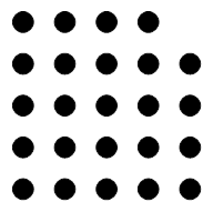
The calibration target needs to be positioned in front of the camera, so that all dots are visible. The geometry of the target needs to be known, i.e. the center positions of the equidistant dots need to be known. From the camera image, the coordinates of the dot centers are measured with sub-pixel accuracy using blob analysis.
Finding the Calibration Target Orientation
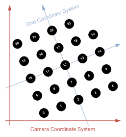
When the target is first positioned, it may be misplaced and rotated.

The goal is now to find the rotation of the target, so that the dots can be numbered according to the target’s numbering scheme. To do so, the dot in the middle is found and its coordinates xc and yc are measured. Next, the four nearest dots are found, sorted counter clock-wise and their coordinates xi and yi are measured. Now, a virtual coordinate system can be established for the grid, with the following coordinates:
$${ P }_{ c }=\left( \begin{matrix} 0 \\ 0 \end{matrix} \right) ,{ P }_{ 1 }=\left( \begin{matrix} 1 \\ 0 \end{matrix} \right) ,{ P }_{ 2 }=\left( \begin{matrix} 0 \\ 1 \end{matrix} \right) ,{ P }_{ 3 }=\left( \begin{matrix} -1 \\ 0 \end{matrix} \right) ,{ P }_{ 4 }=\left( \begin{matrix} 0 \\ -1 \end{matrix} \right)$$
The transformation between the CCS (Camera Coordinate System) and the GCS (Grid Coordinate System) can be formulated as follows:
$$M=\left( \begin{matrix} 1 & 0 & { t }_{ x } \\ 0 & 1 & { t }_{ x } \\ 0 & 0 & 1 \end{matrix} \right) .\left( \begin{matrix} cos(\varphi ) & -sin(\varphi ) & 0 \\ sin(\varphi ) & cos(\varphi ) & 0 \\ 0 & 0 & 1 \end{matrix} \right) .\left( \begin{matrix} { s }_{ x } & 0 & 0 \\ 0 & { s }_{ y } & 0 \\ 0 & 0 & 1 \end{matrix} \right)$$
$$M=\left( \begin{matrix} { s }_{ x }cos(\varphi ) & -{ s }_{ y }sin(\varphi ) & { t }_{ x } \\ { s }_{ x }sin(\varphi ) & { s }_{ y }cos(\varphi ) & { t }_{ x } \\ 0 & 0 & 1 \end{matrix} \right) =\left( \begin{matrix} { m }_{ 11 } & { m }_{ 12 } & { m }_{ 13 } \\ { m }_{ 21 } & { m }_{ 22 } & { m }_{ 23 } \\ 0 & 0 & 1 \end{matrix} \right)$$
With this information and the measured camera coordinates for the center dot and the dots 1 to 4, we can establish the following equations to calculate the six unknowns of the matrix M:
:
$$\left( \begin{matrix} { x }_{ c } & { y }_{ c } & 1 \\ { x }_{ 1 } & { y }_{ 1 } & 1 \\ { x }_{ 1 } & { y }_{ 2 } & 1 \\ { x }_{ 1 } & { y }_{ 3 } & 1 \\ { x }_{ 1 } & { y }_{ 4 } & 1 \end{matrix} \right) \left( \begin{matrix} { m }_{ 11 } \\ { m }_{ 12 } \\ { m }_{ 13 } \end{matrix} \right) =\left( \begin{matrix} 0 \\ 1 \\ 0 \\ -1 \\ 0 \end{matrix} \right)$$
$$\left( \begin{matrix} { x }_{ c } & { y }_{ c } & 1 \\ { x }_{ 1 } & { y }_{ 1 } & 1 \\ { x }_{ 1 } & { y }_{ 2 } & 1 \\ { x }_{ 1 } & { y }_{ 3 } & 1 \\ { x }_{ 1 } & { y }_{ 4 } & 1 \end{matrix} \right) \left( \begin{matrix} { m }_{ 21 } \\ { m }_{ 22 } \\ { m }_{ 12 } \end{matrix} \right) =\left( \begin{matrix} 0 \\ 0 \\ 1 \\ 0 \\ -1 \end{matrix} \right)$$
Once we have obtained the coefficients of matrix M, we can then go and determine the scaling factors sx and sy, the rotation angle φ and the translation vector (tx, ty)T.
The following formulas are used:
$$\left( \begin{matrix} { t }_{ x } \\ { t }_{ y } \end{matrix} \right) =\left( \begin{matrix} { m }_{ 13 } \\ { m }_{ 23 } \end{matrix} \right)$$
$$\left( \begin{matrix} { s }_{ x } \\ { s }_{ y } \end{matrix} \right) =\left( \begin{matrix} \sqrt { { { m }_{ 11 } }^{ 2 }+{ { m }_{ 21 } }^{ 2 } } \\ \sqrt { { { m }_{ 12 } }^{ 2 }+{ { m }_{ 22 } }^{ 2 } } \end{matrix} \right)$$
$$\left( \begin{matrix} { \varphi }_{ x } \\ { \varphi }_{ y } \end{matrix} \right) =\left( \begin{matrix} { tan }^{ -1 }(\frac { { m }_{ 21 } }{ { m }_{ 11 } } ) \\ { tan }^{ -1 }(\frac { { m }_{ 12 } }{ { m }_{ 22 } } ) \end{matrix} \right)$$
You will get two scale factors and you will also get two rotation angles. If the scale factors or the angles are different to a certain extent (they will be slightly different because of measurement errors of course), this hints to a misplaced orientation of the calibration target with respect to the camera so that skew or perspective occurs. In this case the orientation of the calibration target must be checked, so that the calibration target is perpendicular to the optical axis.
Going back one step, we can now use matrix M to calculate the virtual coordinates of the grid dots so that we can properly sort them:
After the transformation with the matrix M the dots can be sorted based on their virtual coordinates in the GCS line by line from bottom to top and left to right within each line very easily.
Please note that the dot at the upper right position (or any other position, but not in the middle) may be missing. This can be done to establish an absolute orientation. nGI can handle targets with a missing dot as well as targets with all dots. When all dots are available, the orientation cannot be determined (the grid may be rotated by 90°, 180° or 270° and this cannot be properly determined). When a dot is missing, the orientation can be fixed up by 90°, 180° or 270° depending on the position of the missing dot in the sorted list. Here is a code fragment that shows how to sort the coordinates of a measured calibration grid:
#include <ngi_sort_calibration_target_coordinates.h>
using namespace ngi;

// container holding the dot centers
std::vector<point<double> > centers;

// someone must somehow measure the dot centers in the image of the
// calibration grid and fill the container
// ...

// sort the grid coordinates
graphics_matrix<double> transformation =
    sort_calibration_grid_coordinates(centers.begin(), centers.end());
Have a look at the sample code in samples/console/calibration_target if you want to learn more about how to work with a calibration target.
Passpoint Transformation
With this set of measured and ordered grid coordinates, you can now properly match them to real world coordinates by means of a passpoint transformation.
Here is a code fragment that shows how to calculate the passpoint transformation matrix:
#include <ngi_geometric_transformation_passpoint.h>
using namespace ngi;


// containers holding the source and destination coordinates
std::vector<point<double> > source;

// container holding the dot centers
std::vector<point<double> > destination;

// someone must somehow provide the point coordinates
// ...

ngi::graphics_matrix<double> transformation =
    ngi::affine_transformation_from_passpoints(
        source.begin(), source.end(), destination.begin());