nGI provides flexible means to visualize images and associated graphical annotations. All the rendering commands go through a portability layer, which directs the commands to various graphics back ends. nGI has a 2D graphics system which is used for visualization of images, curves and geometries. The section Graphics Engines explains the different graphics back ends available within nGI. These engines provide device independence and isolate the actual graphics engine or back end from the graphics interface usable.

The nGI graphics API can be used to draw into a window or into a view. The graphics API can draw images as bitmaps, profiles and histograms as diagrams as well as geometric primitives in outlined and/or filled form.
Context
Before any drawing can occur, you need to create a graphics context. The graphics context holds all information required to draw. The graphics context has the same interface for all selectable graphics engines, but it has a different implementation for each of them. The graphics context is implemented as a class and provides member functions that carry out the actual drawing.
Coordinates
Graphics are drawn within a coordinate system. In order to facilitate easy cooperation with image coordinates, the coordinate system has its origin in the upper left corner, positive x coordinates extend to the right and positive y coordinates extend to the bottom. The graphics system is two-dimensional. There is no z dimension in graphics that would correspond with the z dimension in images. The graphics system is connected to the system of hierarchical widgets. Each widget lives in the coordinate system of its parent widget, but it may establish a different coordinate system for itself and its children. For example, the widget_image shifts its coordinate system by half a pixel right and down, in order to make sure that integer coordinates are in the middle of a pixel. If you draw graphics on top of an image (inside an image_widget), the lines will be centered on the image pixels if you draw them with integer coordinates.

Brush
A brush is needed to fill a geometric primitive. nGI provides a solid color brush. A solid color brush can be created from a color and an alpha value. To create a brush call one of its constructors.

| this code | creates... |
|---|---|
solid_color_brush() |
a black brush (default color) with a default alpha value of 1.0 (fully opaque). |
solid_color_brush(red) |
a red brush with a default alpha value of 1.0 (fully opaque). |
solid_color_brush(rgb(127, 127, 127)) |
a gray brush with a default alpha value of 1.0 (fully opaque). |
solid_color_brush(green, 0.5) |
a green brush with an alpha value of 0.5 (50 % transparent). The background shows through if you draw with a transparent brush. |
solid_color_brush(black, 0.0) |
a black brush with an alpha value of 0.0 (fully transparent). Drawing with a fully transparent brush has no effect, regardless of the color. |
Pen
A pen is needed to outline a geometric primitive. A pen has a certain brush, opacity (alpha), a width, a dash style, a dash offset, a cap style for start, end and dash caps, a line join style and a miter limit. It is used to draw outlines.

The picture shows various pens with different colors and increasing width from top to bottom. The fact that the line ends seem to extend more to the left and right with the thicker lines comes from the fact that a square end line cap is used by default.

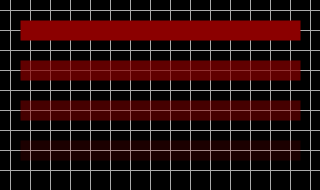
A pen’s opacity or transparency can be adjusted with its alpha value (alpha = 1.0 means fully opaque, alpha = 0.0 means fully transparent). The resulting color is a mixture of the background with the pen color, where the alpha value controls the weight of the mixture.

A pen can have flat, square, round or triangle shaped end caps, as shown in the picture. The caps can be specified separately for the begin and end of the line.
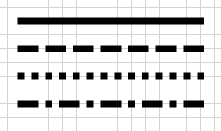
A pen can have various dash styles: solid, dashed, dotted, etc.

The dash pattern can be shifted left or right with the dash offset. Positive values shift to the left, negative values shift to the right. The actual shift amount is the pen width multiplied by the dash offset.

Similar to the end caps, a pen can have also dash caps.


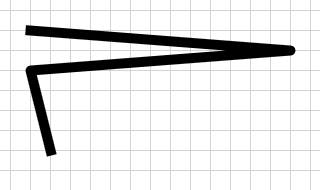

A polygon can have various joins at the vertices: miter join, bevel join, round join.


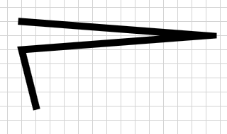
The miter limit controls how far joins can extend, when the angle between the lines is small.